302 Results
View results:
Sort by:

In this article, you will learn how to model and design cable structures in RFEM 6 or RSTAB 9.

To evaluate whether it is also necessary to consider the second-order analysis in a dynamic calculation, the sensitivity coefficient of interstory drift θ is provided in EN 1998‑1, Sections 2.2.2 and 4.4.2.2. It can be calculated and analyzed using RFEM 6 and RSTAB 9.

For the ultimate limit state design, EN 1998‑1, Sections 2.2.2 and 4.4.2.2 require a calculation considering the second‑order theory (P‑Δ effect). This effect may be neglected only if the interstory drift sensitivity coefficient θ is less than 0.1.

Creating a validation example for Computational Fluid Dynamics (CFD) is a critical step in ensuring the accuracy and reliability of simulation results. This process involves comparing the outcomes of CFD simulations with experimental or analytical data from real-world scenarios. The objective is to establish that the CFD model can faithfully replicate the physical phenomena it is intended to simulate. This guide outlines the essential steps in developing a validation example for CFD simulation, from selecting a suitable physical scenario to analyzing and comparing the results. By meticulously following these steps, engineers and researchers can enhance the credibility of their CFD models, paving the way for their effective application in diverse fields such as aerodynamics, aerospace, and environmental studies.

Everything is online. The same is true for the Dlubal licenses for RFEM 6, RSTAB 9, and RSECTION. This article contains information about using and managing online licenses, reserving licenses, checking the license validity, and moving authorizations between the licenses.

The response spectrum analysis is one of the most frequently used design methods in the case of earthquakes. This method has many advantages. The most important is the simplification: It simplifies the complexity of earthquakes so far that the design can be performed with reasonable effort. The disadvantage of this method is that a lot of information is lost due to this simplification. One way to moderate this disadvantage is to use the equivalent linear combination when combining the modal responses. This article explains this option by describing an example.

Our webservice offers users the opportunity to communicate with RFEM 6 and RSTAB 9 using various programming languages. Dlubal's high-level functions (HLFs) allow you to expand and simplify the WebService's functionality. In line with RFEM 6 and RSTAB 9, using our WebService makes the engineer's work easier and faster. Check it out now! This tutorial shows you how to use the C# library by means of a simple example.

The modal relevance factor is a result of the linear stability analysis and qualitatively describes the degree of participation of individual members in a specific mode shape.

To be able to evaluate the influence of local stability phenomena of slender structural components, RFEM 6 and RSTAB 9 provide you with the option of performing a linear critical load analysis on the cross-section level. The following article explains the basics of the calculation and the result interpretation.

When a concrete slab is set upon the top flange, its effect is like a lateral support (composite construction), preventing problems of torsional buckling stability. If there is a negative distribution of the bending moment, the bottom flange is subjected to compression and the top flange is under tension. If the lateral support given by the stiffness of the web is insufficient, the angle between the bottom flange and the web intersection line is variable in this case so that there is a possibility of distortional buckling for the bottom flange.

For the stability verification of members using the equivalent member method, it is necessary to define effective or lateral-torsional buckling lengths in order to determine a critical load for stability failure. In this article an RFEM 6-specific function is presented, by which you can assign an eccentricity to the nodal supports and thus influence the determination of the critical bending moment considered in the stability analysis.

With the Steel Design add-on, you can design structural steel components in the event of fire using the simple design methods according to Eurocode 3. The component temperature at the time of the design check can be determined automatically according to the temperature-time curves specified in the standard. In addition to considering a cladding for fire protection, it is also possible for you to take account of the beneficial properties of hot-dip galvanization.

The CSA S16:19 Stability Effects in Elastic Analysis method in Annex O.2 is an alternative option to the Simplified Stability Analysis Method in Clause 8.4.3. This article will describe the requirements of Annex O.2 and application in RFEM 6.
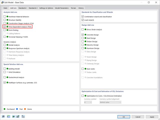
This article shows how the “Time-Dependent Analysis” add-on is integrated in RFEM 6 and RSTAB 9. It describes how to define input data such as the time-dependent characteristics of the material, how to determine the type of analysis and how to specify loading times.

As for the previous generations of Dlubal programs, an integrated interface with Autodesk Revit is now also available for RFEM 6 and RSTAB 9. This article will provide some general information about the interface as well as the Dlubal-relevant structural objects and parameters in Revit.

The Steel Joist Institute (SJI) previously developed Virtual Joist tables to estimate the section properties for Open Web Steel Joists. These Virtual Joist sections are characterized as equivalent wide-flange beams which closely approximate the joist chord area, effective moment of inertia, and weight. Virtual Joists are also available in the RFEM and RSTAB cross-section database.
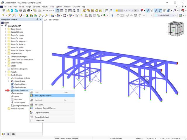
In the RFEM 6 and RSTAB 9 programs, it is possible to group objects based on different criteria. Hence, objects that meet the defined criteria can be selected and edited at the same time. This is possible with the “Object Selection” tool, which is comparable to “Special Selection” in RFEM 5. This article will show you how to group objects with “Object Selection" as a new guide object of RFEM 6 or RSTAB 9.

Windbreak structures are special types of fabric structures which protect the environment from harmful chemical particles, abate wind erosion, and help to maintain valuable sources. RFEM and RWIND are used for wind-structure analysis as one-way fluid-structure interaction (FSI).
This article demonstrates how to structural design windbreak structures using RFEM and RWIND.
RWIND 2 is a program for generating wind loads based on CFD (Computational Fluid Dynamics). The wind flow numerical simulation is generated around any building, including irregular or unique geometry types, to determine the wind loads on surfaces and members. RWIND 2 can be integrated with RFEM/RSTAB for the structural analysis and design or as a stand-alone application.
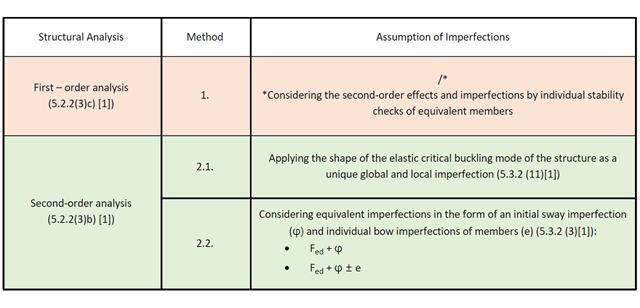
This Knowledge Base article discusses different methods for a stability analysis provided in EN 1993-1-1:2005 and their application in the RFEM 6 program.
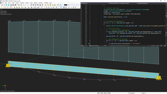
The API for RFEM 6, RSTAB 9, and RSECTION is based on the WebService concept. To get a good introduction to the subject, the following article will explain a further example in C#.

Consideration of p-δ Second-Order Effects in RFEM 6 and RSTAB 9
This article summarizes the advantages of working with parameterized models in RFEM 6 and RSTAB 9.

This article shows you how to define different types of member transverse stiffeners in RFEM 6 and RSTAB 9. It also shows you how to consider them in the design as well as the calculation of members with 7 degrees of freedom.
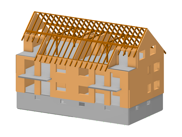
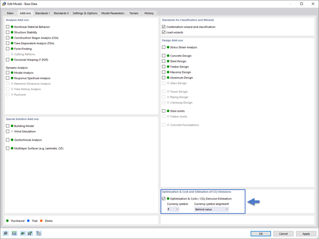
This article shows you how to estimate CO2 emissions in RFEM 6/RSTAB 9.

This article discusses the options available for determining the nominal flexural strength, Mnlb for the limit state of local buckling when designing according to the 2020 Aluminum Design Manual.
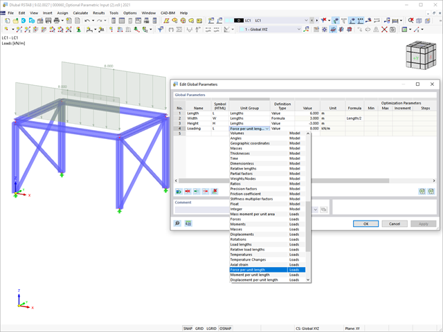
This article will show you how to optimize global parameters in RFEM 6 according to different aspects.

RFEM and RSTAB programs provide parameterized input as an advantageous product feature to create or adjust models by means of variables. This article will show you how to define global parameters and use them in formulas to determine numerical values.

This article will show you how to use the Torsion Warping (7 DOF) add-on in combination with the Structure Stability add-on to consider cross-section warping as an additional degree of freedom when performing the stability analysis.
This article will show you a practical example of how to determine critical load factors and corresponding mode shapes in RFEM 6.